Overland Tech and Travel
Advice from the world's
most experienced overlanders
tests, reviews, opinion, and more
Factory vs. aftermarket
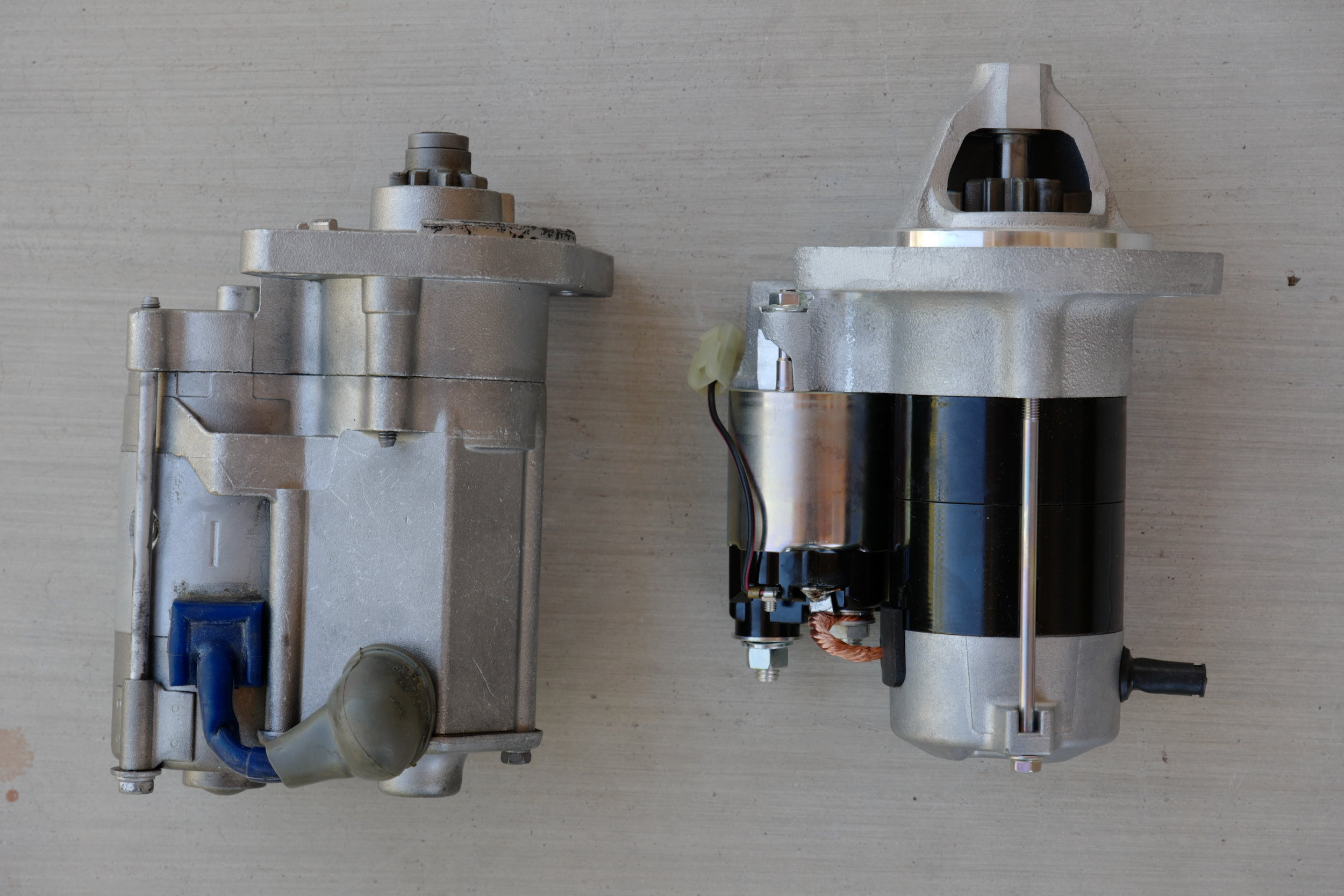
Aftermarket starter on the left; Toyota starter on the right
If you’ve ever turned over an engine by hand you know it’s no easy thing to do. You’re working against a lot of internal friction, plus the compression as each piston rises on the firing stroke. Your starter has to do the same job, except a lot faster. So it clearly needs to be built well.
Take a look at these two starters for a Land Cruiser F or 2F engine—an aftermarket unit on the left and a factory Toyota unit on the right. If you’re not familiar with how a starter works, notice the small gear visible at the top of each unit. When you turn the ignition key to start the engine, that gear slides forward and engages the flywheel behind the engine, and spins it rapidly to enable the ignition to catch and start the engine. Once it starts and you release the key, the gear slides back out of engagement.
It should be obvious that that gear is subjected to a great deal of stress—which is why the factory starter has a nose cone that supports the end of the shaft on which the gear slides, hugely increasing its stiffness (and also possibly helping keep random dirt and debris away from the shaft and gear).
Now look at the aftermarket starter. No nose cone, no support for the gear. Cheaper to make, for sure.
Which would you expect to last longer?
More praise for high-tooth-count ratchets
Top to bottom: and 80-tooth Snap-on 1/2-inch ratchet, a 72-tooth 3/8-inch Britool ratchet, and a 72-tooth 1/4-inch Proxxon ratchet.
I’ve written here and there in these pages and elsewhere of my strong preference for ratchets with a high tooth count—at least 72 or 80 (some have even gone beyond that).
The advantage to this is the ratchet handle does not have to pivot as far to engage the next tooth (or teeth, as most ratchets engage multiple teeth). And that is a significant advantage when working in tight spots where you do not have much room to swing the handle. An 80-tooth ratchet needs just 4.5 degrees of movement to advance the socket, whereas, say a 48-tooth ratchet would need 7.5 degrees. It might not sound like much, but sometimes it means the difference between very limited access and none at all.
I had another demonstration of this advantage the other day, when I had to replace the clutch master cylinder on the FJ40. For some reason the cylinder I bought interfered just barely with the brake master cylinder’s booster, so I had to loosen the latter from inside the footwell. And the upper left bolt of the bracket sits just so between a reinforcing strut and the brake pedal, so that swing room for my ratchet was reduced to . . . well, just abut 4.5 degrees. However, that was no problem for the 80-tooth 3/8ths ratchet I had on hand.
You might think that the strength of the ratchet head would suffer with such a fine engagement, but in fact modern ratchets are probably stronger than older, coarser models due to better metalurgy and that multi-tooth engagement. One of my favorite tool investments is a Snap-on SX80-A flex-head 1/2-inch ratchet, with an 80-tooth head and an 18-inch handle—the same length as a common, non-ratcheting breaker bar used for loosening the tightest large nuts on transmissions and suspensions. And that’s how I use this, knowing that Snap-on makes the same ratchet with a 24-inch handle. Obviously they have confidence in that head.
The truth about aftermarket "high-performance" brakes.
Few people reading this would argue that the single most important component of your vehicle is the braking system. Everything else—engine power, handling, comfort, fuel economy, off-pavement capability, number of USB outlets—is secondary to the critical need to be able to stop that vehicle safely and quickly, time after time.
Yet despite that single-purpose, critical function, there are a lot of myths circulating about brakes, how they work, and how they can be improved—and a lot of those myths originate from, or are promulgated by, companies trying to sell you something.
In terms of physics, brakes do exactly one thing: They convert the kinetic energy of the moving vehicle into thermal energy, i.e. heat. All brakes function this way, whether disc, drum, or Fred Flintstone’s feet. In fact, even the parachute on a top-fuel dragster converts the kinetic energy of the vehicle into heat, through friction with the atmosphere; it is simply dissipated more diffusely in the dragster’s slipstream.
The energy those brakes must convert does not increase linearly with speed; instead it increases with the square of speed (kinetic energy equals mass times velocity squared). Thus a vehicle moving at 50 mph requires four times as much energy conversion to stop as one moving at 25 mph, and one moving at 100 mph requires sixteen times as much. Given the same speed and the same vehicle weight, the heat produced by stopping is also the same, whether it is done via cast-iron drum brakes on a Series 2 Land Rover or the carbon-ceramic discs on a Porsche GT3.
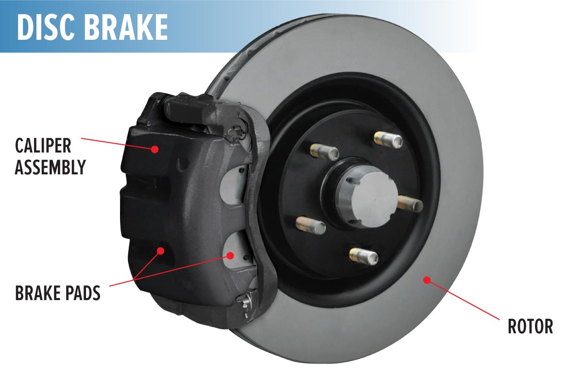
The basic operation of a brake goes like this: When the driver presses the brake pedal, the pedal pushes a plunger into a hydraulic cylinder filled with brake fluid—a viscous substance resistant to heat. The cylinder, called the master cylinder, is connected to a brake caliper in each wheel via tubes. The caliper wraps around the perimeter of the brake disc, and incorporates a piston on each side (sometimes several), which bear against brake pads made of friction-resistant material. The master cylinder forces the brake fluid, which is essentially incompressible (more about that later) through the tube and against the pistons in the caliper, which in turn push the brake pads against the disc, squeezing the disc (also called the rotor) with tremendous force, creating friction and slowing the vehicle.
The drum brake, which has virtually disappeared except on the rear axles of the cheapest economy cars and Toyota Tacomas (see here), is different. Instead of a flat disc there is a cast-iron drum shaped like a flat pan with vertical sides, turned vertically so it rotates with the wheel. The master cylinder pushes against a slave cylinder (a quaint term, no?) which in turn pushes a friction-resistant brake “shoe” against the drum. Drum brakes have (mostly) gone the way of flathead V8s and carburetors because they retain more heat (more on that soon) and don’t work well when wet.
There have been many advances to the basic hydraulic braking system. Originally (and still in a few applications) each caliper employed only one piston and the caliper could slide slightly back and forth. The piston pushed one brake pad against the disk while simultaneously pulling the opposite pad against the other side. This was much less efficient than the later multi-piston calipers. Modern brake calipers on high-performance sports cars can employ six or even eight opposed pistons.
Virtually all brakes today are power-assisted via a vacuum-operated device incorporated into the master cylinder. This reduces braking effort, sometimes hugely in the case of a heavy truck. Also, all brake systems are now (by law) dual-circuit: The master cylinder is essentially two master cylinders combined in line, each of which operates on both front brakes and one rear brake. This redundancy insures that if one circuit fails, the vehicle will still retain reasonable stopping power.
A big advance in the efficiency of brakes arrived with anti-lock braking systems (ABS), which use a simple sensor at each wheel to monitor revolutions of the wheel. If a sensor detects a wheel locking up (i.e. turning slower than the others or stopping altogether), the ABS computer pulses power to that brake so that it unlocks. This system reduces braking distances and increases the driver’s control over the vehicle. (To see why a turning tire stops shorter than a skidding tire, look here.)
As vehicles have become heavier—and wheel diameters larger—manufacturers have been installing larger and larger-diameter discs in their brake systems. Most disc brakes are now ventilated—the disc comprises two discs joined by a vaned center section to dissipate heat more effectively. Thanks to such advances—as well as better tire compounds—average braking distances have been steadily shrinking.
Mostly.
Obviously it’s easier to stop a light vehicle than a heavy one. By extension we can state categorically that it is easier to stop, say, a stock FJ60 Land Cruiser than one that has been modified with an ARB winch bumper and a Warn 9,000-pound winch, a rear spare/jerry can rack, a roof rack, a 60-liter fridge, a drawer system, an auxiliary fuel tank, and . . . you get the picture. With surprising suddenness your 5,000-pound Land Cruiser x velocity squared can become a 7,000-pound Land Cruiser x velocity squared.
I discovered the results on our own FJ60 on a biological survey in Mexico’s Sierra Madre some years back. This 60 had a turbodiesel engine conversion plus most everything on the list above. And on a steep, winding descent of about 3,000 feet, the brake pedal began to feel mushier and mushier, even as I downshifted to use engine braking. By the time we reached the plains the brakes had seriously deteriorated, and only regained effectiveness after ten minutes of cooling down.
I had experienced classic brake fade.
Brake fade can occur essentially two ways. First, a brake pad can overheat from extended application—such as a long descent—and form a slick glaze on its surface. When this happens the brake pedal will still feel firm, but increased pressure will have little or no effect. Second, the brake fluid itself can heat to its boiling point. When this happens, the fluid turns to a gas—and gas, unlike the fluid, is compressible. So your desperate standing on the pedal just compresses the gas in the calipers and does little to squeeze the brake pads. This is what we experienced. The condition can be aggravated if you don’t regularly flush your brake system. Brake fluid is hygroscopic, meaning it absorbs water, and since water has a much lower boiling point than pure brake fluid, old, contaminated fluid can cause premature boiling and fade.
Of course even stock vehicles with no weighty accessories bolted to them can be subject to brake fade, and even if no calamities ensue when it occurs it is a deeply unsettling experience. The logical first response is, “I need better brakes!” Indubitably true, but the path to obtaining them is fraught with hype and numerous ways to spend lots of money for very little if any gain.
Let’s start with that brake fluid. Brake fluid is graded on a DOT scale, based on its minimum boiling point, both dry (uncontaminated with water), and wet (contaminated). Most braking systems come from the factory filled with DOT 3 fluid, which has a minimum boiling point of 401ºF dry and 284º wet (see now how much water can degrade your brakes?). Dot 4 fluid is rated at 446º and 311º minimum, respectively, and DOT 5.1 fluid carries a 518º and 374º rating. So simply spending 20 bucks or so upgrading your brake fluid can give you a full 100-degree margin over DOT 3 before gassing occurs. Note that these standards are minimums; many premium brake fluids will perform well above that and will say so on the label. And what happened to DOT 5 fluid? That’s a silicone-based fluid as opposed to the glycol base of DOT 3, 4, and 5.1. You can mix glycol-based fluids all you like, but cannot mix glycol and silicone fluids.
It will do little good to install better, high-temp brake fluid if your brake pads are sub-standard. Most vehicles come from the factory with organic-compound pads, or NAO (non-asbestos organic). These are sufficient for most use—they are quiet, don’t create much brake dust, and are easy on the discs—but if overheated can be subject to the glazing we discussed earlier. Semi-metallic pads, which are a mixture of iron, copper, steel, and graphite in an organic matrix, are significantly more resistant to glazing, at the expense of (sometimes) more noise, more dust, and faster disc wear—and of course slightly higher cost. A third type of brake pad, ceramic, attempts to solve the noise and dust issues of semi-metallic pads, and is resistant to fade, but less aggressive and generally not recommended for heavy-duty use, especially in cold climates—although the technology is still advancing..
So if your braking system is in good order, you’ve upgraded your brake fluid and switched to semi-metallic pads, and you’re still experiencing brake fade, what then? (I’ll refrain from suggesting, “Leave some of that crap at home.”) It might be time for a more drastic upgrade.
And that’s where marketing hype gets really tricky.
Many commercial kits (as well as a whole bunch of do-it-yourself threads on forums) “upgrade” the front brakes—where most braking occurs—simply by means of replacement calipers with more and/or larger pistons and larger pads than the originals. More pistons equals more squeeze and better braking, right?
Not so fast.
Remember all that kinetic energy we’re turning into thermal energy every time we stop? That energy (heat) has to be dissipated to enable repeated stops—or a safe descent down a mountain grade—without overheating the pads or brake fluid. And the way that heat is dissipated is through the brake disc. So if you install more powerful calipers on your existing discs, here’s what’s likely to happen: You’ll take the vehicle out for a trial run around town, and be impressed at the increase in stopping power. Those new four- or six-piston calipers grab that disc right now. Awesome. So you’ll then head confidently to that long downhill that resulted in a scary spongy brake pedal last month, and . . . oh. Whoa. Halfway down, the pedal feels like it’s got an entire bag of Sta-Puft marshmallows between it and the calipers. That’s because you’ve installed the means to inject more heat into the braking system without installing the means to get rid of it. As long as you’re just trundling around town you’ll get some benefit from the more powerful calipers, but under prolonged application all they’re likely to do is make your fade problem worse.
Okay . . . plan B then. Let’s install a set of those fancy (and awesome-looking) cross-drilled brake discs. You know, like Porsches and Ferraris have? Cross-drilled discs stay cooler, right, with all those holes?
Sorry . . . wrong again.
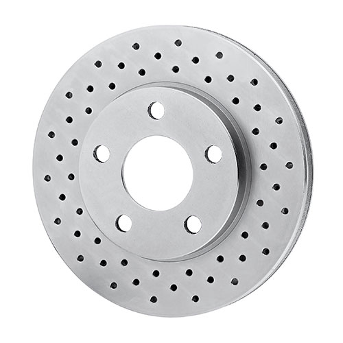
Cross-drilling of brake discs began in the early days of disc brakes, when existing pad materials and adhesives tended to outgas strongly when heated. Cross-drilling relieved the fractional layer of (compressible, remember) gas the pad would exude between it and the disc. But modern brake pads exhibit virtually none of this outgassing. More importantly, a cast-iron brake disc relies on its mass to absorb and dissipate heat. When you drill a bunch of holes in it, you are reducing that mass. (One company actually boasts that its drilled discs are 16 percent lighter than non-drilled discs.) Some arguments—especially from those who sell them—still maintain that the ventilation and added surface area of cross-drilled discs provide enough cooling to offset the loss of mass. But the further I investigated, the more testimonials I read from objective experts in the field who called nonsense. At best, many referred to any cooling effect as a wash, and several pointed out how often cross-drilled discs wind up plugged with brake dust—a giveaway that not much air flow is occurring through those holes (unlike the well-documented radial flow through the center vanes of a ventilated disc). Add to that the fact that, even when properly cast in and chamfered rather than simply drilled, cross-drilling can introduce stress risers into the disc that promote cracking, and you have a powerful argument against it, no matter how stylish it looks. (And if you look at the ads from companies who sell them you’ll be amused at how many mention the style factor as an actual reason to spend your money.)
The sole theoretical advantage to drilled discs mentioned by those same experts was a slightly enhanced initial “bite” in wet conditions, when the holes might provide an exit for surficial water on the disc. But brake pads quickly squeegee water off that surface anyway, so even this attribute is of questionable value in the face of the expense and loss in mass of a drilled disc.
Thus we can say pretty confidently that replacing your plain brake discs with cross-drilled discs of the same size will probably result in no reduction in fade, and could conceivably exacerbate it.
(Incidentally, the above does not apply to disc brakes on motorcycles, since a motorcycle disc is a solid rotor rather than a vented, double-sided unit. On a solid rotor, cross-drilling does at least theoretically create some turbulent cooling flow.)
What about the more recently popular slotted discs? Slots actually perform a different function than drilling. The edges of the slots perform a microscopic scraping function on the pad, keeping the pad surface fresh and possibly forestalling glazing. While they won’t in themselves enhance cooling or prevent heat-related fade, they might help forestall the fade resulting from overheated pads of inferior composition. Be advised, however, that slotted discs, as you might expect, will wear out pads more quickly than solid discs, and are likely to exacerbate any brake-dust issues.
Inevitably, aftermarket manufacturers are now offering discs that are both cross-drilled and slotted. At least the slots will provide some function, and where the slots are there is less room for the pointless holes . . .
All this leads to a logical conclusion. Once you’ve optimized your brake fluid and brake pads—and assuming the rest of your braking system is operating as it should—the only sure way to add braking power and reduce the chance of fade is to install, surprise, larger brakes—specifically discs of larger diameter and/or width, with calipers to match. Sometimes this is possible within the constraints of your existing wheels and front end design, sometimes it is not.
Automobile manufacturers are perfectly aware of this. To give you a random example—outside the realm of overland vehicles but one with which I’m familiar—when Porsche upgraded the 1983 911SC to the 1984 Carrera, including a 15-percent bump in power, they improved the braking by increasing the width of the front brake discs from 20 to 24 millimeters, while keeping the diameter the same at 289mm. For the significantly more powerful Turbo of the same era, they increased both the diameter and the width of the discs, to 300 and 32mm respectively. Those were the largest brakes that could fit within the factory 16-inch-diameter wheels. When Porsche added even more power, they switched to larger-diameter wheels as well to accommodate larger discs.
There is one minor exception to the only-bigger-is-better rule. If you look at different aftermarket discs, you’ll notice significant variations in the spacing of the center cooling vanes. Inexpensive discs will be made with more widely spaced slots, which means there is both less mass in the disc to radiate thermal energy, and less radial air flow as well. The one way an aftermarket disc of the same dimensions as the stock disc might outperform it is if the aftermarket disc has a higher density of vanes, and thus weighs more than the stock disc. StopTech, for example, makes a replacement disc for the Tacoma that is stock diameter, but weighs over a pound more, thanks to more closely spaced vanes. That translates to more thermal capacity.
A comparison of vane spacing on a vented brake disc.
Looking at our own class of vehicles, it is all too easy to find “high-performance” brake kits comprising nothing but inexpensive stock-sized replacement discs that have been cross-drilled and/or slotted. Some of the claims for these border on outrageous.
Note that line, “Improves stopping power up to 30 percent over stock brake rotors.” Seriously? Thirty percent meaning 30-percent shorter stopping distances? Or thirty percent less fade? I’d love to see an independent test of that claim. Also, there is simply no chance that their “custom slots” do any cooling, and they will more than likely increase dust due to the scraping function. Finally, check the “reducing heat” claim at the top, which we know from physics is impossible. The only component in this kit likely to modestly improve braking performance is the semi-metallic pads, if they are replacing stock pads—and those certainly won’t “reduce noise.” That’s a stunning amount of misinformation in a single ad.
Finding kits to actually upgrade brakes is much, much harder, in part because it so often requires installing larger-diameter wheels as well. TRD offers a front disc upgrade kit for Tacomas that increases the disc size from 319mm to 332 mm but still fits within the stock wheels. That’s a worthwhile enhancement.
Redline Land Cruisers offers a Big Brake kit for the front of FJ40s, 55s, and 60s that increases the disc diameter from 12 inches to a full 13.3 inches and includes calipers from a later 100-series Land Cruiser—a significant upgrade. But the kit requires a switch to 17-inch wheels for clearance (the company also wisely recommends rear discs, a larger master cylinder, and a proportioning valve to correctly balance front-to-rear braking force). They also mention a big brake kit for 16-inch wheels, but I’ve not received any more information on that one.
I’ve seen a few other legitimate kits for various vehicles, but there is far more in the way of chaff to wade through to find it. The good news is, I suspect for the majority of us a simple upgrade to better pads and fluid will solve anything but chronic brake fade. If that won’t do it, at least now I hope you’ll be better able to distinguish hype from fact.
And if you really want to drill holes in something, maybe you could take up carpentry . . .
Quality . . .
It’s no secret that I’m a believer in high-quality gear, whether it’s the vehicle, accessories, tools, camping equipment, or personal accoutrements. I also try to buy American-made products when possible (and when they meet my standards, which is not always the case).
But for certain products there simply is no longer a U.S.-made (or even North American-made) choice.
Recently I was in the market for a new Gore-Tex parka, and turned to Arc’Teryx, a company I can modestly claim to have helped publicize in their early days, when I reviewed gear for Outside magazine. I was impressed with the quality of Arc-Teryx’s products—even among a suite of superb contemporaries such as Marmot—and at the time they were making their clothing in Canada.
Sadly, that no longer seems to be the case. The Beta AR jacket I bought was made in, of all places, Myanmar (Burma to many of us).
But my initital disappointment more or less evaporated when I examined the jacket closely. Try as I might, I could find not a single flaw in its construction—indeed, the closer I looked the more impeccable were the details and stitching. In the end I had to admit it was fully the equal of any of the company’s early efforts.
That doesn’t mean I’m happy that the manufacturing of so many thousands of products has shifted overseas to save labor costs here—and, make no mistake, that is the sole reason to do so—but it did serve as a reminder to me that quality is not intrinsic to any geographic locale. So perhaps it’s now more important than ever for consumers to actually pay attention to what they buy, and evaluate it on its merits rather than any arbitrary prejudice.
New MAXTRAX Xtreme
It’s well-known that I’m a fan of the original MaxTrax, and have defended them against cut-price copies. I’ve also noted that I refuse to use the company’s all-caps MAXTRAX spelling, which as a grammarian I find wincingly annoying (I compromise with MaxTrax). Now . . . sigh . . . the company is torturing me again with their new product, named the Xtreme. Ugh.
I grit my teeth and continue, because the new product, a prototype of which I received recently, looks to be a significant leap in the technology of composite recovery mats. Why? Because the teeth, or studs, of the new mat are made from hard-coated aluminum rather than molded-in nylon. And . . . they are user-replaceable.
As anyone who has used them knows, the salient disadvantage of composite recovery mats is that, if you allow too much wheel spin while attempting to climb onto them, the studs can melt, significantly and permanently reducing the effectiveness of the product. Recent mats using harder plastic studs helped but did not cure the issue. The Xtreme might just do so.
The composite base of the new mat is the same reinforced nylon material as the original MaxTrax, which I and many other testers have found to be superior to the polyethylene used by some lower-priced competitors. There is also extra reinforcement in the bottom webbing. Combining that with the aluminum studs should provide vastly improved durability.
As you might expect, the Xtreme is a bit heavier than the standard MaxTrax—8.9 versus 7.4 pounds each. But at 18 pounds per pair that’s still lighter than even perforated aluminum sand mats.
They are not, however, cheaper. Retail on the Xtreme will be $449 a pair. I remember being scandalized at the idea of the original $300 MaxTrax—until I used them. I suspect our perspectives will continue to evolve as long as such price increases are backed up by such meaningful improvements.
The only three knots you need for paracord lashing
In my opinion nothing beats a ratchet strap for securing cargo. Cheaper cinch straps—even the superior style with the roller buckle—just can’t be cinched tight enough to reliably secure heavier and potentially dangerous items.
But it’s not always possible to use ratchet straps. Often you’ll simply run out of your supply, or the hooks won’t fit where you need to secure a load. Sometimes with a bulky roof-rack load you might need to run your lashing back and forth a dozen times to prevent flapping.
Time for the paracord.
Parachute cord has come a long way since its original application. Now you can find it everywhere from those ubiquitous “survival” bracelets and wrapped “tactical” knife handles to—ready?—the Hubble Space Telescope, where astronauts from the space shuttle Discovery used 35 feet of it to resecure loose thermal blankets protecting the instrument.
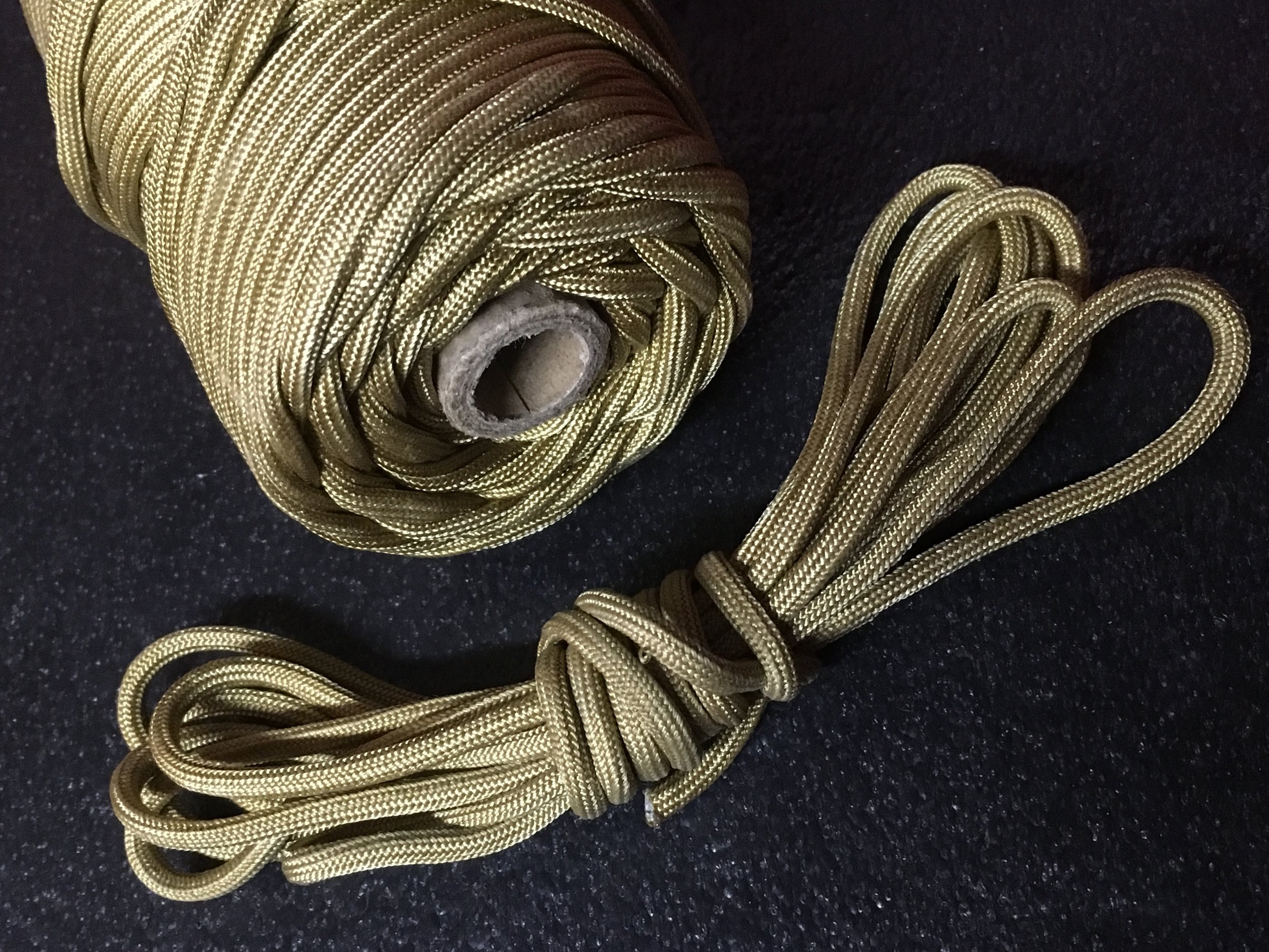
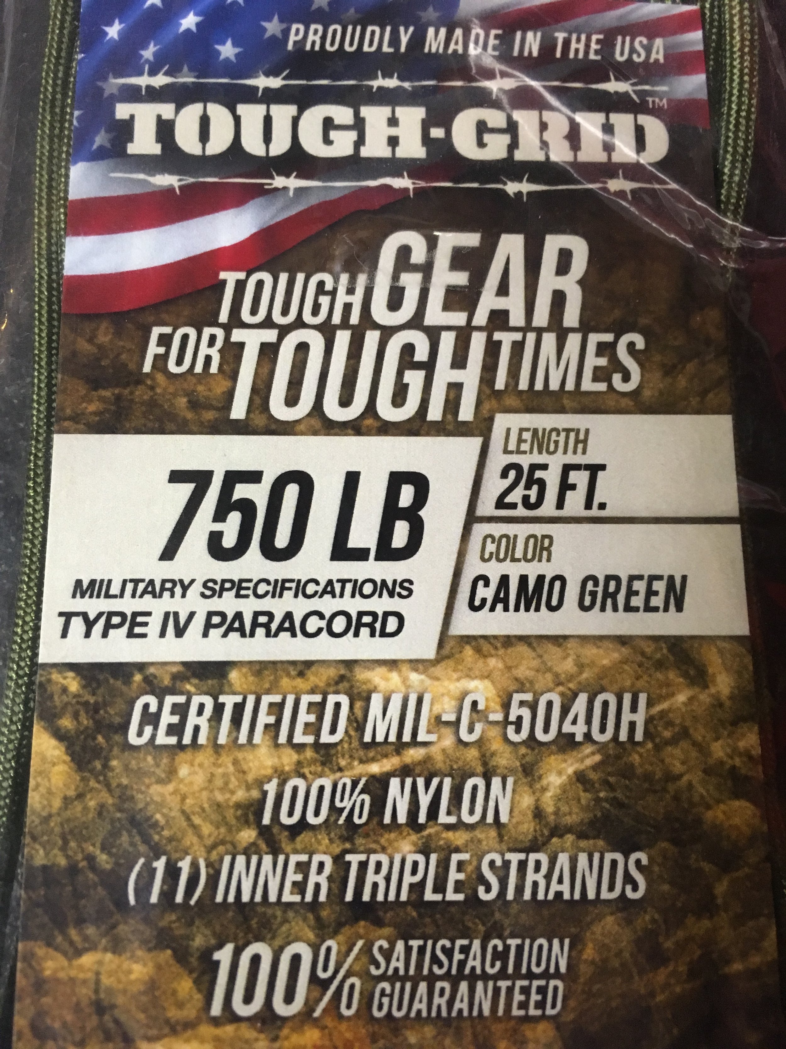
That ubiquity has spawned a lot of substandard variations of the authentic product. Genuine mil-spec nylon paracord will advertise its conformity to military standard C-540H Type III (“550” paracord, indicating its rated breaking strength in pounds), or C-540H Type IV (“750” paracord, again indicating breaking strength). If you pull apart the end of a length of paracord you can confirm authenticity by counting the individual cords within the kernmantle sheath. Genuine mil-spec paracord will have between seven and 11 of them, and each cord will comprise three twisted strands (cheaper paracord might have fewer cords made from only two strands). On genuine mil-spec paracord one of the inner cords will be a contrasting color; this is a marker for the manufacturer.
Even genuine mil-spec paracord is inexpensive enough that keeping a couple hundred feet in the vehicle for odd jobs is affordable. Of course, you can opt for larger and more expensive kernantle cordage, even Kevlar if you want the ultimate in strength. But 550 or 750 paracord is pretty stout, as long as you keep in mind that a knot—any knot, to a greater or lesser degree—will reduce its strength by up to 25 percent.
Once you’ve determined the need for a fabbed up lashing and have cut the length you need, don’t neglect to fuse the end, otherwise the interior cords can protrude and snarl and your work will look decidedly less than pro. I work the kernmantle sheath over the end, so when I apply a flame it (usually) melts nicely and encapsulates the cords. Just make sure you have a solid, tight blob. I find that putting the flame next to but not right on the end helps melt the cord neatly.
Now you need to secure that cargo securely. Paracord has two characteristics that can work with and against you. It’s a bit stretchy, which makes it easier to tell when you’ve pulled it tight enough but can let the load shift if you haven’t. And it’s fairly slippery, which makes it easier to pull tight across duffels and other luggage, but which also means knots can come loose if not chosen correctly and tied properly.
To ensure that, you need know only three: a bowline, a trucker’s hitch, and a sheetbend.
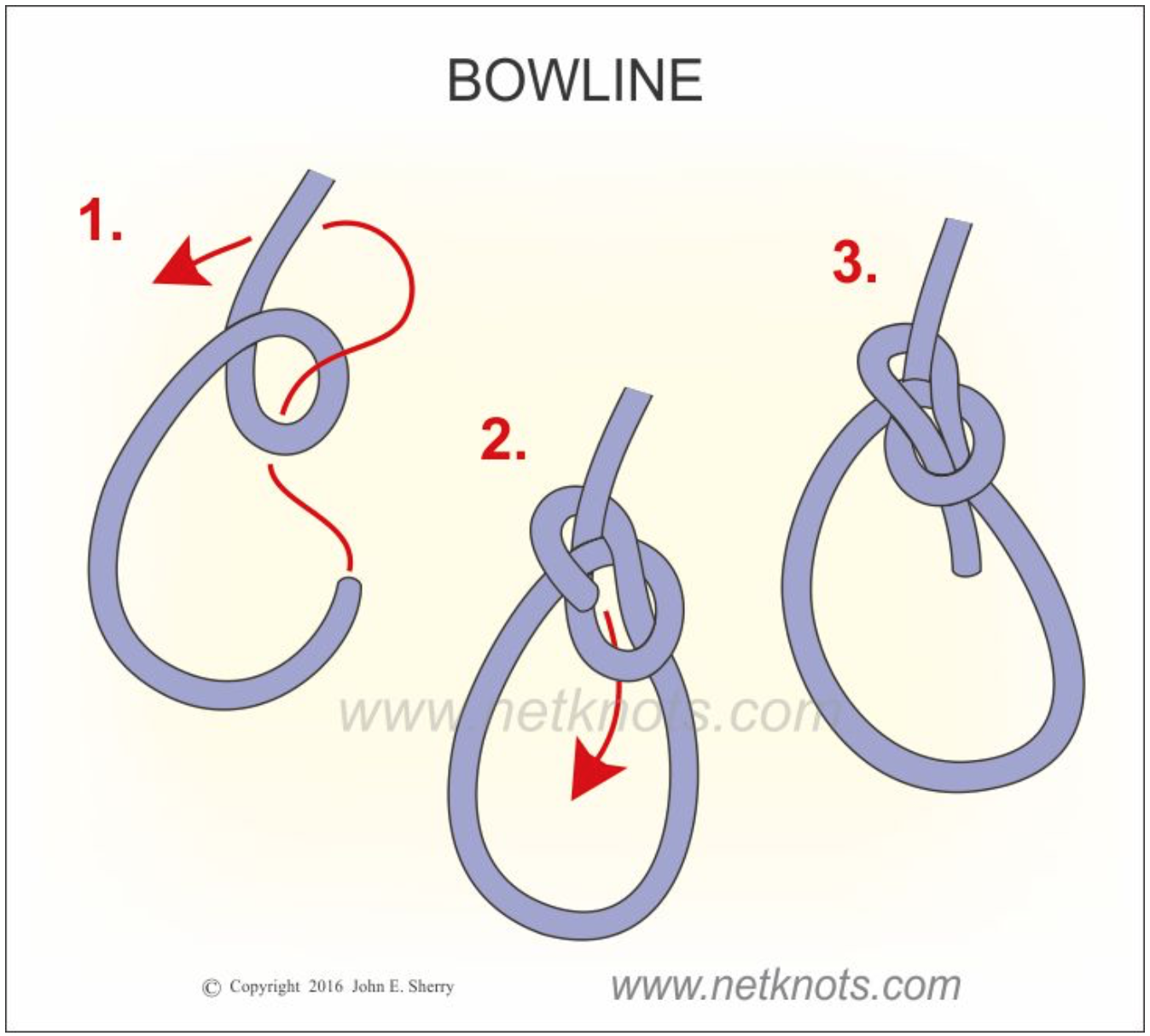
The bowline is the best way to make a secure loop, to tie the first end of your paracord to the roof rack or cargo eyelet. (I’ve blatantly lifted the still images here from the excellent site netknots.com, because I urge you to go there and watch the easy-to-follow animations of these knots, and dozens more.) The bowline is strong, it weakens the rope less than some other knots, yet it is easy to undo.
At the other end, you want to pull that cord as tight as possible and secure it so it won’t loosen. The trucker’s hitch actually functions as a jive pulley to multiply the force you’re pulling with, and when tied off properly will not slip.
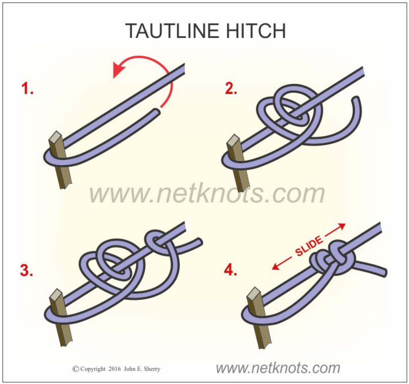
When using paracord I suggest augmenting the netknots instructions. In part three, they finish off the knot with a single loop (basically a half hitch). However, paracord can slip if secured thusly. I strongly suggest looping the end of the cord through twice, then looping it the opposite direction below, so you in effect add a tautline hitch, like this:
Do this finishing knot right up against the “pulley” loop. Just as with the bowline, the trucker’s hitch unties easily, and in fact the slippery half hitch you tied to use as the “pulley” will pop loose simply by pulling on either end of the cord.
The last knot you’ll use if you need to join two cords that are each too short: the sheet bend. It’s an incredibly simple knot, almost a square knot except the free end of the second (blue here) cord tucks under as shown.
For extra security you can double the knot as in the diagram. The brilliant thing about the sheet bend is that it will effectively join two cords or ropes of different diameter. Just remember to use the smaller line for the second (blue) part of the knot.
And the brilliant thing about all these knots is that they’re useful in hundreds of other situations. So cut yourself a three-foot piece of mil-spec paracord and practice them until they’re second nature. They’ll serve you well.
Quality, seen and unseen
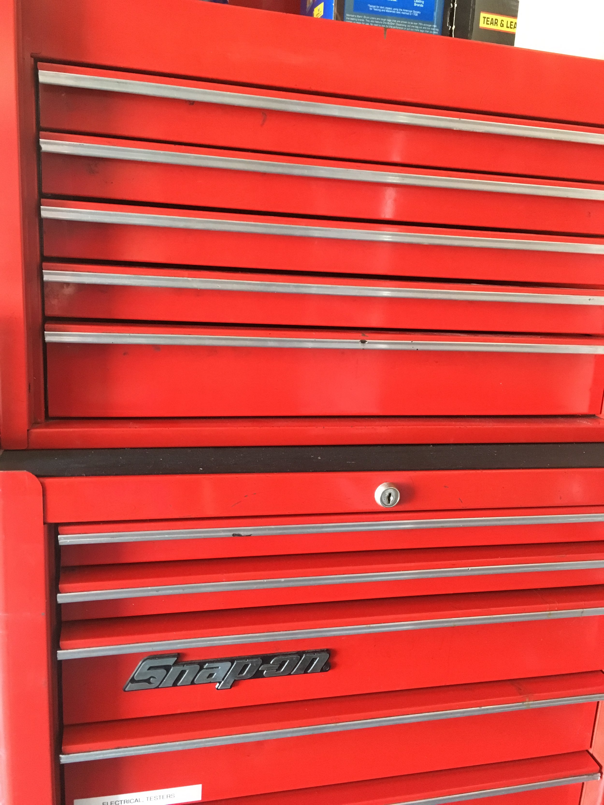
For several years I’ve stored my “in-town” automotive tools in a modest older Snap-on rolling chest combination (which I bought used). But it’s been getting really crowded recently, and I’ve been thinking about augmenting or replacing it. The decade-old Craftsman chest out at our desert place is larger, but I didn’t want to just swap the two as I still need a full complement of tools out there as well.
By sheer coincidence I was at an acquaintance’s house last week to deliver a gate opener I’d sold him, and it turned out he had recently bought the entire remnant stock of Kobalt tool chests from the local Lowe’s home improvement stores. Kobalt had been the chain’s store brand for years, but recently they switched to Craftsman—which, as you might know, is now owned by Stanley Black and Decker rather than Sears. In my mind this switch is actually a step down: Recent made-in-China Craftsman tools that I’ve examined in their packaging show noticeably poorer finish than the older made-in-America products, poorer in fact than the few Kobalt tools I’ve purchased to review.
Anyway, my friend had scored several dozen of Kobalt’s top-of-the-line stainless-steel-clad tool chests, and quickly unloaded all of them at fire sale prices. He had exactly one left, and it happened to be a tall, narrow, 27-inch-wide model, which is the only configuration that will fit in the in-town garage. So I bought it for a song.
Back at home I had to pull the drawers to unload it and get it into position. And that gave me the opportunity to look past the beautiful stainless exterior and the nifty soft-close drawers. What I noticed made me pull apart that plain old red Snap-on chest to examine it as well. And that’s where significant differences showed up. Drawers out, the Snap-on cabinet was noticeably heavier and more torsionally rigid than the top box on the Kobalt. Where Snap-on used nuts and bolts and spot welds to assemble pieces, the Kobalt had been assembled almost exclusively with pop rivets—in fact I found several stems from those rivets still inside the cabinet. Both brands incorporate smooth roller-bearing drawers, but when I re-installed the Snap-on drawers they each slotted perfectly into their slides and snicked home effortlessly, while the Kobalt’s drawers proved to be a real pain to get properly lined up. I had to carefully fit each side in each slide to prevent it simply falling out, then guide the assembly in until it clicked back together—after which, I should note, each worked perfectly, including the soft-close function.
Don’t get me wrong: The Kobalt chest is a very nice item and I’m glad I bought it, especially at the price. I’m sure it will serve my amateur mechanic needs adequately, as I’m only in those drawers a dozen times per month, rather than dozens of times per day as a pro would be. But it was clear that the Snap-on chest would hold up to that kind of use far better than the Kobalt would. (And I managed to squeeze the Snap-on chest into another corner of the garage.) Snap-on certainly puts a hefty price premium on its products, and it is inarguable that a good part of that premium is strictly due to the name and cachet, but at least you get the excess you pay for.
In a larger context, it points out the obvious fact that external looks aren’t everything. It’s the engineering underneath that determines quality.
Classic Kit: The capstan winch
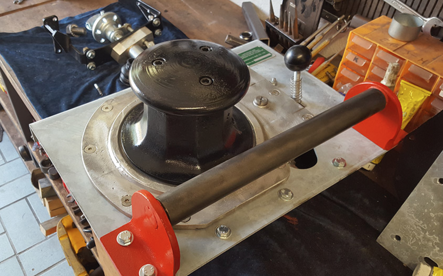
If you’ve ever crewed (or skippered) a sailboat longer than 20 feet or so, you’ve probably used a capstan winch to control lines such as the jib and spinnaker sheets. A basic capstan winch comprises a vertical drum geared so it will only turn one way (always clockwise on a sailboat). When you wrap the line around the drum (again, clockwise) two or three times, you can more easily control the forceful pull of the sail. The friction of the wraps helps prevent the line being pulled away from you. If you need more power to sheet in a sail in a breeze, a a fitting on top of the drum allows you to insert a crank for extra leverage. There are more elaborate capstan winches with two speeds, self-tailing mechanisms—and electrically powered winches that eliminate the need for manual cranking.
For many years, a capstan winch could also be ordered as a factory option on Land Rovers and a few other vehicles. Visually the vehicle-mounted capstan winch was very similar to our sailboat winch; however, it was powered through a gearset from a driveshaft usually connected directly to the vehicle’s crankshaft via a sliding coupler. The worm-drive gearset reduced the 600 or 700 rpm of an idling engine crankshaft to just a dozen or so turns per minute of the drum (which, curiously, rotates counterclockwise on every one I’ve seen).
A capstan winch at LR-Winches. Engagement lever is at upper right. The rope is led under the roller from the anchor or object to be moved.
A capstan winch has an entirely different method of operation from the common, horizontal-drum electric, hydraulic, or even PTO winch with which we’re familiar. You don’t store line on the capstan, and it cannot use steel cable. Instead you carry a separate, low stretch rope—traditionally 3/4-inch manila or an equivalent natural fiber—of whatever length you chose, with a hook on one end.
Let’s say you’re driving your Series II 88 along a forest track and you come across a downed tree blocking the way. Pulling it out of the path would go like this:
Position the vehicle so the winch has a clear route to drag the tree off the path. Leave the engine idling, transmission in neutral (obviously), parking brake on and, if possible, the wheels chocked as well. (If you have a hand throttle you can bump up the engine rpm a bit.) Wrap a strap around the tree and connect your winch rope to it with its hook. Take the free end of the rope back to the vehicle, run it under the roller guide and around the drum three or four times counterclockwise in an ascending spiral, then lay the free end of the rope off to the left of the vehicle as you’re facing the front. With the coils of the rope around the drum still loose, engage the lever to connect the drum to the gearset and the drum will begin turning slowly—but the loose rope will simply slip around it. Now stand back from the vehicle a few feet and pull on the free and of the rope to tighten the wraps around the drum. The drum will grab the rope and begin pulling on the downed tree, as you take in the rope fed you by the winch. You now control the speed and engagement of the winch simply by pulling or slacking off on the rope to tighten or loosen it around the drum. Once the tree is off the path, let the rope go slack, disengage the gearset with the lever, and de-rig. It’s that simple.
Of course you can also connect the rope to a standing tree or another vehicle to free yours if it is bogged; however, since the capstan winch requires someone standing outside the vehicle to operate the winch, it’s nearly mandatory to have a second person in the driver’s seat to steer the vehicle and stop it once it’s free. Solo vehicle recovery with a capstan winch can be a very dicey operation indeed.
Consider the situation pictured below. Tom Sheppard was in Mali in 1978, en route to Timbuktu, driving his Land Rover Velar—that’s right, the original prototype of the Range Rover—and towing a trailer full of fuel and water, when a section of mud proved a bit deeper and stickier than was apparent from the driver’s seat.
Tom’s Range Rover was equipped with a Fairey capstan winch cleverly hidden behind the grille—note the horizontal roller on the bumper. To deploy it one simply unscrewed the center grille section, a matter of a couple of minutes. However, Tom was, as is common with him, traveling solo. Therefore he first unloaded all 21 (!) jerry cans from the trailer, decoupled it from the Range Rover, and recovered the Range Rover with aluminum sand (i.e. mud) ladders. Then he positioned the Range Rover in a spot where he could use the capstan winch to recover the trailer, re-connect it to the Range Rover, reload all 21 jerry cans, and continue on his way.
(Tom’s story made me remember the tour Roseann and I got of the Gaydon Museum, courtesy Land Rover historian extraordinaire, Roger Crathorne. I looked up one of the photos, which shows, in addition to Roger and me, one of the Range Rovers used on the 1971/72 Trans-Americas Expedition—and there was a capstan winch peeking out from behind the grille.)
The capstan winch’s labor-intensive method of operation, combined with its modest power—most were rated for around 3,000 pounds, as was the rope used on them—saw them fade from popularity with the increasing availability of horizontal-drum electric winches of considerably higher rating. Yet the capstan had its advantages. It could work all day without overheating or stressing the vehicle’s electric system, and its line capacity was essentially unlimited—if you needed to rig a 200-foot pull, all you needed was a 220-foot rope. And that labor-intensive method of operation gave the operator instant control over the procedure—let off on the rope tension and the pull stops instantly. The capstan winch, with its leisurely speed, hands-on attitude, and natural-fiber rope, always struck me as, well, the friendly winch compared to the whining, straining, ozone-smelling electric winches of today (hugely capable though they certainly are). Go ahead, laugh.
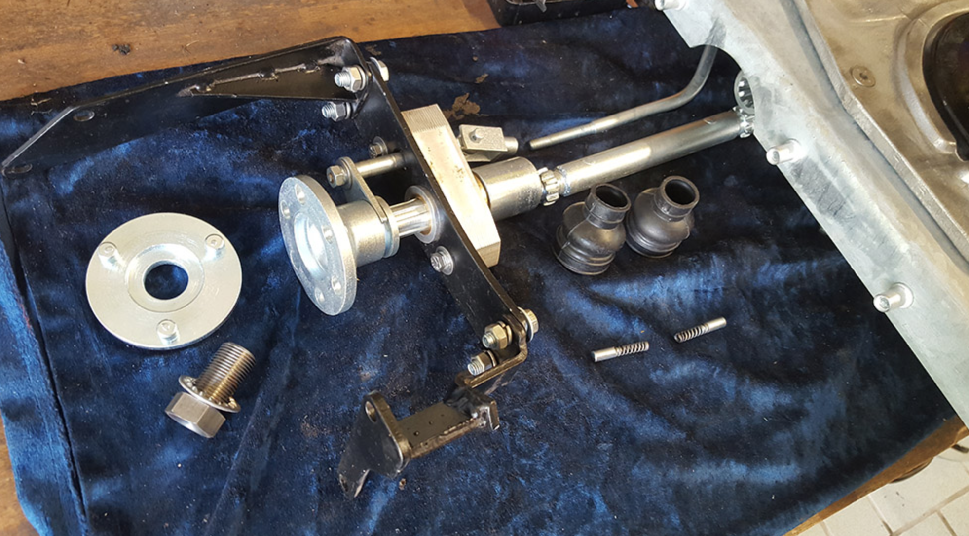
This is the driveshaft and engagement mechanism that allows the capstan to be powered off the front of the vehicle’s engine.
You can still, very occasionally, spot a vehicle equipped with a capstan winch—virtually always a Series Land Rover. If you own a Series Land Rover and have a hankering for a curious and historical piece of very useful equipment, you can still buy one (or parts for one) through sources such as the experts at LR-Winches (where most of these images originated). You can even buy a synthetic rope suitable for a capstan winch, from LR-Bits.co.
But I’d recommend sticking with the manila rope. It’s just . . . friendlier.
For a . . . curious . . . installation of a capstan winch, see here.
Hint: When using “Search,” if nothing comes up, reload the page, this usually works. Also, our “Comment” button is on strike thanks to Squarespace, which is proving to be difficult to use! Please email me with comments!
Overland Tech & Travel brings you in-depth overland equipment tests, reviews, news, travel tips, & stories from the best overlanding experts on the planet. Follow or subscribe (below) to keep up to date.
Have a question for Jonathan? Send him an email [click here].
SUBSCRIBE
CLICK HERE to subscribe to Jonathan’s email list; we send once or twice a month, usually Sunday morning for your weekend reading pleasure.
Overland Tech and Travel is curated by Jonathan Hanson, co-founder and former co-owner of the Overland Expo. Jonathan segued from a misspent youth almost directly into a misspent adulthood, cleverly sidestepping any chance of a normal career track or a secure retirement by becoming a freelance writer, working for Outside, National Geographic Adventure, and nearly two dozen other publications. He co-founded Overland Journal in 2007 and was its executive editor until 2011, when he left and sold his shares in the company. His travels encompass explorations on land and sea on six continents, by foot, bicycle, sea kayak, motorcycle, and four-wheel-drive vehicle. He has published a dozen books, several with his wife, Roseann Hanson, gaining several obscure non-cash awards along the way, and is the co-author of the fourth edition of Tom Sheppard's overlanding bible, the Vehicle-dependent Expedition Guide.

